cadmeister-thai@uelthai.co.th

DL, a 3D supporting tool, is used for improving quality of die layout design during the design stage.
Due to the 3D die layout designs enabled by DL, designers can foresee and take measures against any problems that may take place in the post-process stages (of die designs and numerical control/NC) and also in the field.
The previous examinations and responses ensure a process of manufacturing without re-work.
This capability enables users to calculate the center of mass based on the data of model shape, and decide the starting point.
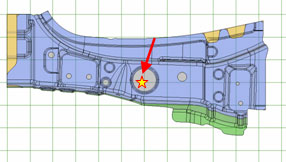
The commands enable consideration of the press/cam directions without pending or compromising the processes of assessment.
It has the capability of suitably adjusting the unit and sequence of rotation even if a die layout designer indicates a press direction for rotation angle of a model through the use of number of decimal places.
The data can be output in XML or CSV formats.
(the "HitTiming" command, the "AbruptWallMeasurement" command, the "Undercut" command, the "TrimCondition" command, the "Pierce_Condition" command)
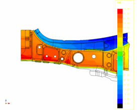
DL has the embedded capabilities below for assessment during the phase of process design.
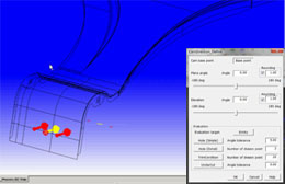
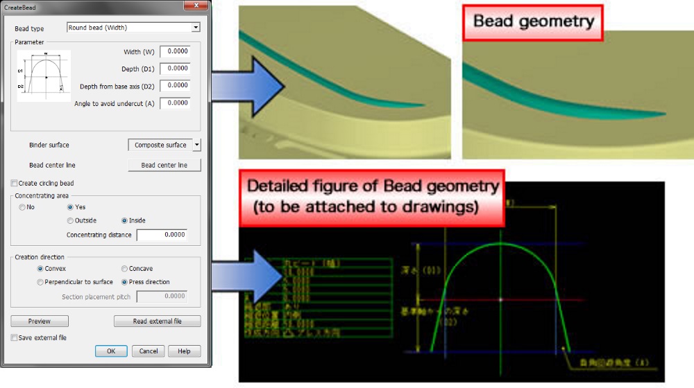
This command enables a simultaneous creation of Bead geometry and detailed figures thereof through simple operations. The detailed figures will be attached to drawings
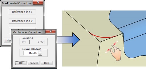
This command enables a creation of a curve that indicates a maximum of R for fillet processing. The curve can be created through intuitive operations of input.
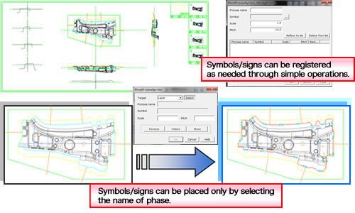
Placing symbols/signs at each drawing is bothersome.
This command enables an easy one-time placement of symbols/signs in each drawing of individual phases through simple operations. Users can register their symbols/signs that they use.
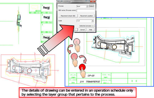
Creating operation schedules is bothersome.
This command enables an easy creation of operation schedules through intuitive operations.
The "Hole_ProcessAllocation" command schedules the processes for piercing.
The "PierceList" command outputs the data of holes.
This command helps an easy examination of layout designs due to the capabilities below: displaying the data of shapes and specifications for a specific press machine on a palette window; and setting the machine on the same screen.
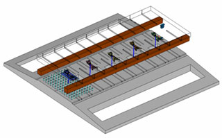
The commands enable users to place pierced metal fittings in holes and provisionally place parts of a press machine.
They also convey the data to the post-process phase of die design in order to decrease the workload of die design.
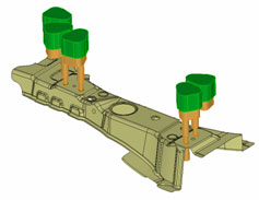

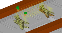
This command creates a‘Scrap’shape based on the shape data, and supports examinations of drop direction and drop locus.
This command creates a 'Scrap' shape based on the shape data, and supports examinations of drop direction and drop locus.

UEL (Thailand) Co.,Ltd.