cadmeister-thai@uelthai.co.th
PHONE
096-9506570
cadmeister-thai@uelthai.co.th
096-9506570

PRESS supports designing press dies. It has three key capabilities: design support, modeling support, and post-process support.
The post-process support is further categorized into capabilities of solid verification, creation of drawings, data for order placement, and coordination of machining.
PRESS’s dedicated commands support the creation of back surface and sectional dies, selection of springs, and placement of standard parts, based on the product shapes during the initial stage of designing.
After the designing is finished, parts lists can be automatically created through the use of parts attributes.
Also, drawings can be checked by executing the commands of interference test and die structure verification. Furthermore, CAM system can be coordinated through the use of machining features.
Commands for the Initial Stage of Design
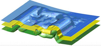
The "Create_FuzzyOffsetSurface" command
This command creates back surfaces that are needed in order to create a Structure based on a panel shape. (Note: a Structure refers to a ferrous die that accepts a press die 'Insert'.)
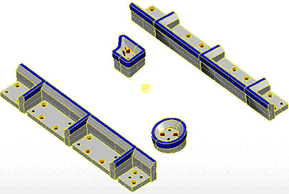
The "CreateSectionalDieShape" command
The "CreateSectionalDieShape" command enables a creation of sectional dies in order to shape trimming blades, steel cutters and flanged blades. Also, it utilizes a special capability of shaping a 'Scrap Cutter' . (Note that Scrap Cutter is a blade that cuts off unnecessary margins from a sheet shaped by press forming.)
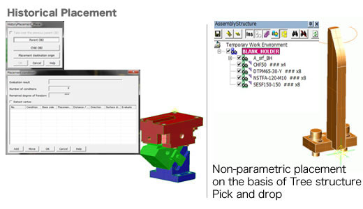
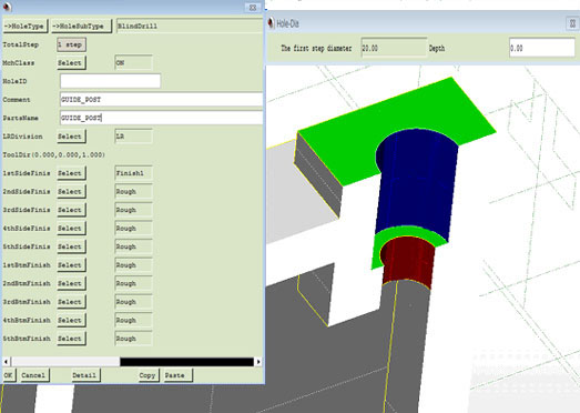
The "CastHole" command
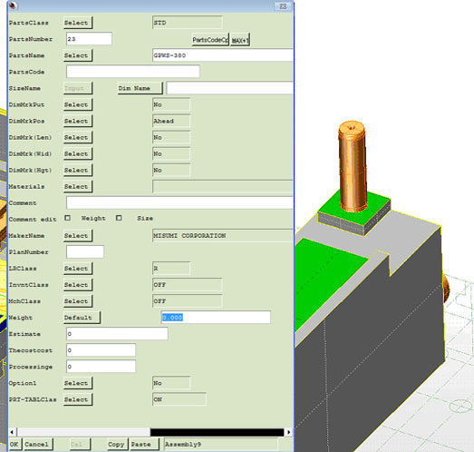
Standard parts and constituent parts such as Guides and U grooves can be placed by trial-and-error attempts.
The attempts can be repeated till the positions are fixed during the Initial Stage of Consideration. These commands support the process.
The commands for creating shapes characteristic to press die support the designs of structure.
Information can be added to the items that should be listed on a parts list,
such as part name, part number and manufacturer name. Also, each item can be customized.
Machining features for plane surfaces, curved surfaces and holes can be added and transmitted to CAM.
This capability supports die verification such as interference check, press composition verification, and scrap fall consideration.
The commands creates parts lists through the use of the added attributes of parts.
The dedicated commands supports a creation of 2D drawings. They create balloons based on parts attributes, and create finish symbols based on machining features.
UEL (Thailand) Co.,Ltd.


 TH
TH IN
IN VN
VN