cadmeister-thai@uelthai.co.th
PHONE
096-9506570
cadmeister-thai@uelthai.co.th
096-9506570

MOLD CREATOR, a strong support for 3D mold design, can be used for all phases of mold design: consideration of formability, nesting design, detailed design, creation of drawing, and creation of data for order placement.
The strength has been proven by records such as a more than 30% reduction of design phase workload in 3 through 6 months after an implementation of MOLD CREATOR.
MOLD CREATOR is effective in reducing design mistakes and reworks, improving design quality, automating order placement of parts, decreasing the workload of drawing creation, automating plate machining, and using 3D data for other relevant processes.
Consideration of Mold Formability
Any causes for poor mold shaping and formability can be detected at an early stage in order to prevent efficiently any degradation of mold quality and design reworks.
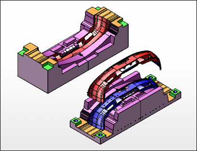
Simple Split
Split patterns of a mold model can be visually and quickly understood. The capability of 'Simple Split' is a strong support for reviewing designs and considering parting lines.
Capabilities of Creating PL Surfaces (for Holes)
The command for creating PL Surfaces (parting line surfaces) creates a new PL Surfaces through the use of outer boundary lines of a cavity/core section.
The command for creating PL Surfaces for holes recognizes automatically holes of open composite surfaces, and fills them through the use of base surface.
There is also a command for filling in a large hole that enables the hole to be filled in without losing connectivity with the adjacent surfaces, provided that hole boundary lines are indicated on open composite surfaces.
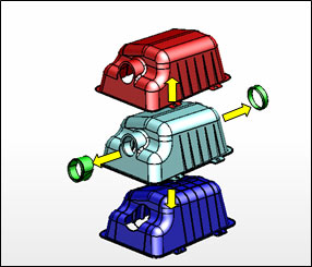
Split
Any complicated mold models can be split easily through the use of PL Surfaces.
Large-scale surface models as well as solid models can be split.
Mold Layout
An easy layout is enabled only by inputting division lines, penetration category, and offset amount for individual mold models.
Note that layout as well as splitting are implementable for surface models.
Assignment of Ejector Pins (E Pins)
This capability enables automatic adjustments of the lengths of ejector pins based on the considerations of the length of mold shape, provided that the surfaces of mold shape and a core-nested solid model is specified.
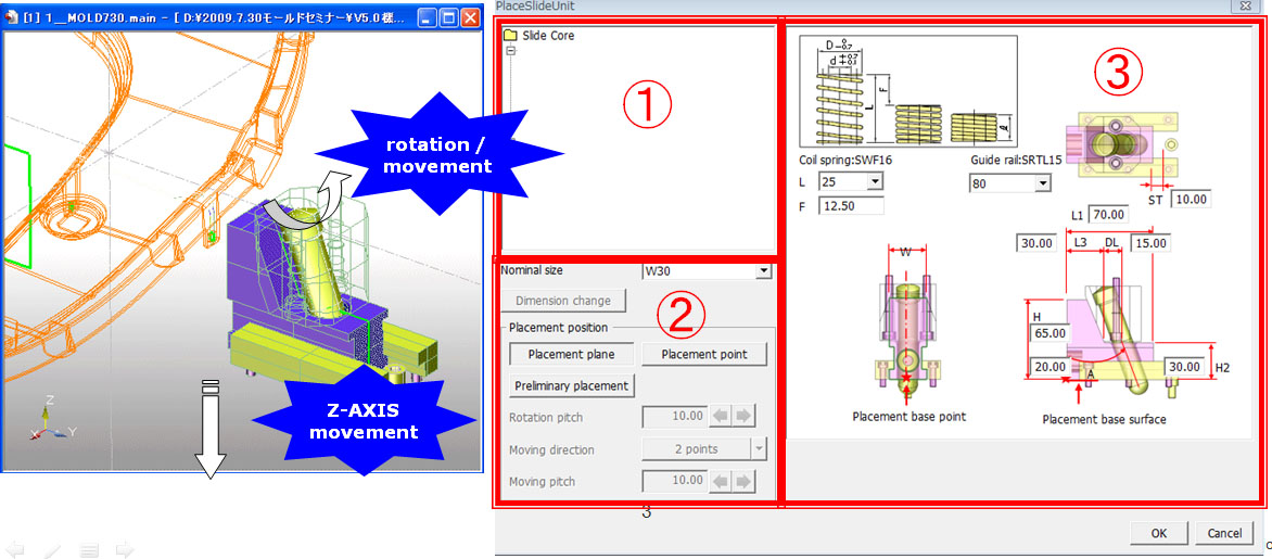
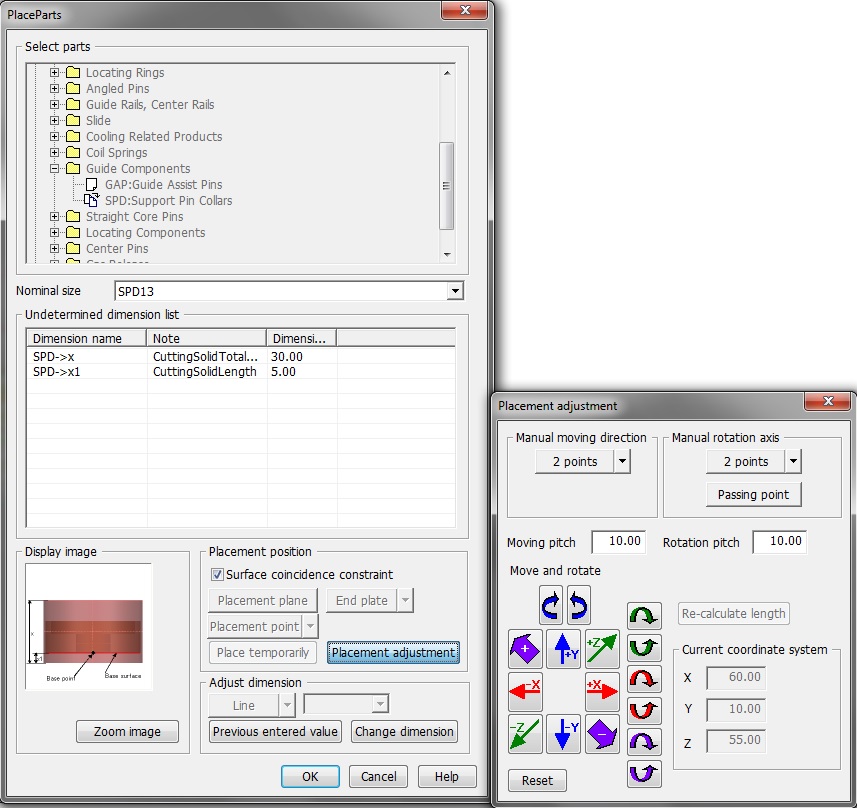
Placement of Slide Unit
Individual dimensions of a Slide Unit can be changed by directly specifying in the dialogue box as shown below.
Sizes and positions can be adjusted by a function of temporary assignment.
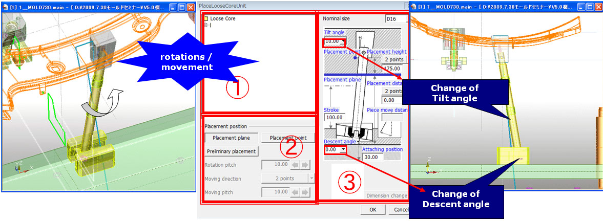
Placement of Tilting Core Unit
The individual dimensions of a Tilting Core Unit can be changed by directly specifying in the dialogue box as shown below. Sizes and positions can be adjusted by a function of temporary assignment.
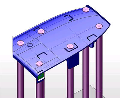
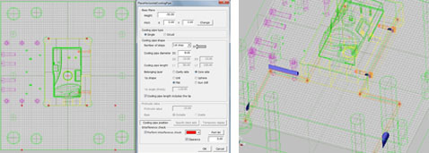
Placement of Cooling Pipes
Cooling pipes can be placed or moved through a trial-and-error approach of conceptual design.
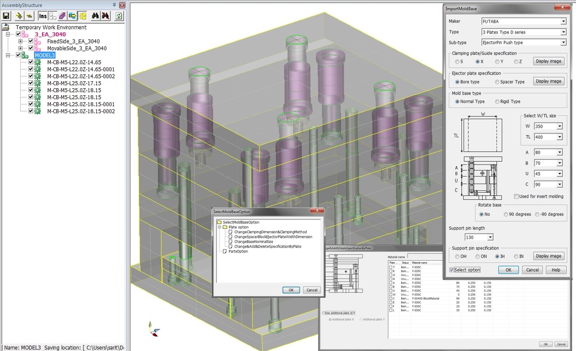
Placement of Mold Base
A mold base that fits any changed or added specifications of plates and parts can be imported into a standard type of mold. Also, the plates and parts have been created to constitute an Assembly Structure. Thus, multiple designs can be concurrent created in order to reduce a design period.
Placement and Edit of Parts
Standard parts and user-defined parts can be specified, placed and edited.
The nominal sizes and actual sizes as well as placement positions can be adjusted through temporary placement.
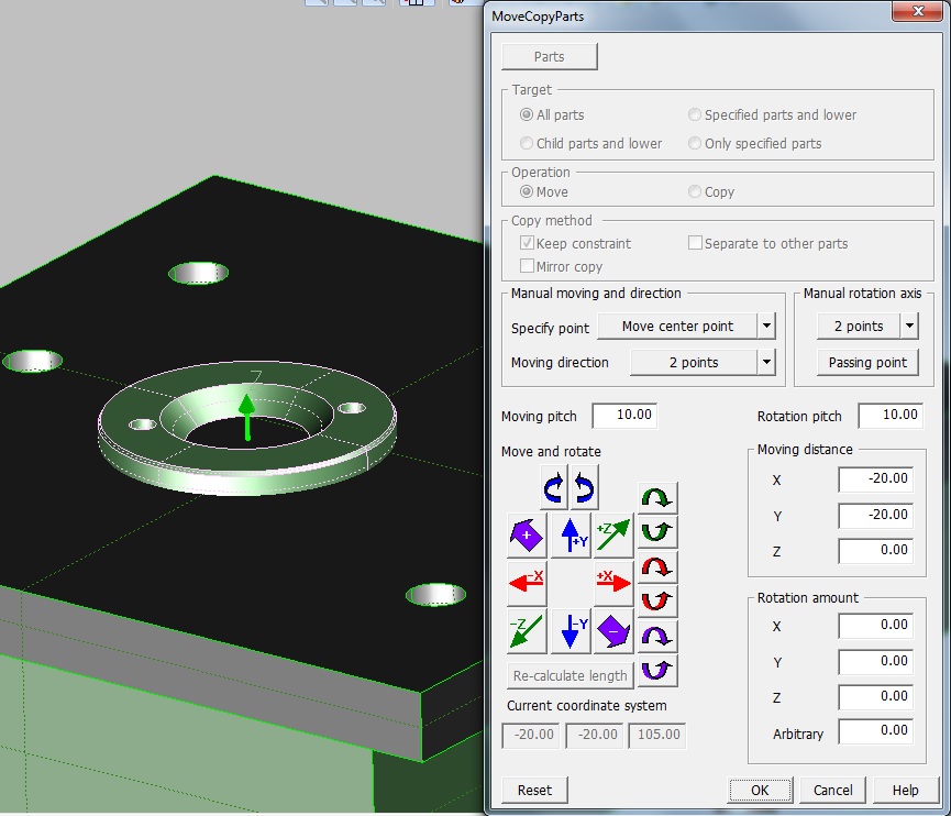
Move and Copy of Parts
Parts that have been created and assigned can be moved and copied in the direction of axis or any specified direction at a specified pitch. Also, they can be revolved and copied. Placement and Copy of Parts
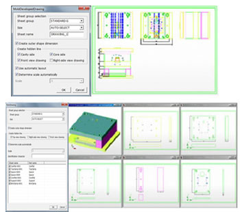
Creation of Drawings
3D mold constituent parts can be expressed collectively at one time in drawings such as assembly drawings, mold development views, and part drawings.
The drawing deliverables can automatically import projection views of shapes as well as the external dimensions.
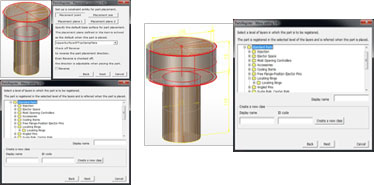
Tool for Registering Parts
Constituent parts necessary for designing a 3D mold can be easily registered through operations assisted by Wizard. A set of parts as well as individual parts can be easily registered likewise.
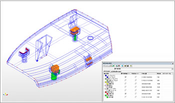
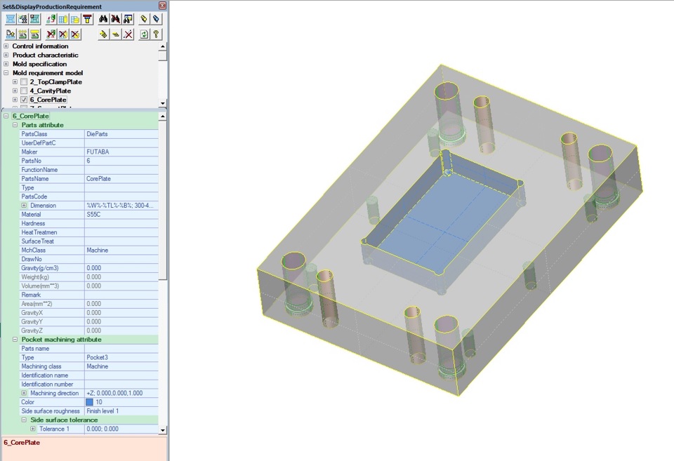
Setting and Displaying CAD Attribute Data
Part attributes, machining attributes, and tolerance attributes can be set for the parts that comprise a mold.
CAD attribute data of a palette window and models’ elements are mutually linked, and thus users can easily confirm them by displaying alternately.
Parts lists, hole lists, and pocket lists can be output on the basis of data that have been set. Assigned CAD attribute data can be imported in CADmeister-LITE where they are displayed and confirmed.
UEL (Thailand) Co.,Ltd.


 TH
TH IN
IN VN
VN