 EN
EN
 TH
TH
 IN
IN
 VN
VN
[Figure 6: Scrap cutter line study]
Integrated 3D CAD/CAM System "CADmeister 2022" Launched
- Significant renewal of CAM functions, optimization of both design and production, contributing to shortening of mold production time –
UEL Co., Ltd. (former company name: Nihon Unisys Excellence Co., Ltd., hereinafter referred to as UEL) will launch a new version of its 3D integrated CAD/CAM system, “CADmeister 2022,” start from September 2022.
CADmeister was launched in July 2005, and is the only domestically produced 3D integrated CAD/CAM system that has been adopted by a total of over 30,000 sheets, mainly by mold manufacturers.
UEL will continue to reflect market trends and customer feedback in our products, actively enhance and improve the functions of CADmeister, maintain and expand international competitiveness in the manufacturing industry, contributes to further efficiency in design/production operations.
[Overview]
In "CADmeister 2022", we have renewed the CAM and strengthened the processing functions in order to realize high-quality and high-efficiency processing in mold manufacturing.
In addition, by optimizing the 3D design through cooperation with IoT and analysis technology and strengthening cooperation with the post-process, it contributes to a significant reduction in the mold production period.
[Version upgrade function]
The main functions that have been enhanced in "CADmeister 2022" are the following four points.
- CAM enhancements
- High-quality & high-efficiency machining functions
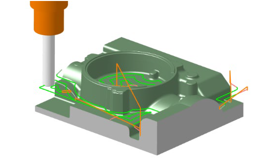
C&G Systems Co., Ltd. (Head Office: Shinagawa-ku, Tokyo; President: Seiichi Shiota; hereinafter referred to as CGS), which has been forming an alliance since 2009. All 3DCAM functions of CAM-TOOL (path calculation engine, path optimization function, etc.) "CAMX" equipped with is added. In roughing, it is possible to create a path with a smooth and stable cutting load that enables high-speed and high-efficiency machining. In finishing machining, the NC data configuration point alignment function realizes smooth machining operations and high-precision surface quality. Realizes high-quality and high-efficiency machining of molds through direct carving of high-hardness materials.
 [Fig. 1: High-speed rough machining by constant-level rough orbital machining]
 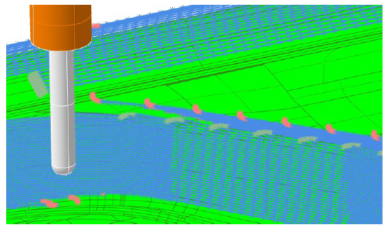 [Figure 2: Equal-height finish - high-quality alignment of constituent points]
- Unmanned processing promotion function
function Added the “Button die (Note 1) hole shape creation function”. It has become possible to automate button die hole drilling of press dies,
which is often manned, for Alignment of physical objects (Note 2) at the processing site . The hole depth is automatically determined in consideration of the
product surface shape and button die size, and it is possible to automatically create Scrap holes (Note 3) and anti-rotation hole shapes. By linking with the CADmeister drilling function, it supports automation of button die drilling without tool interference.
 [Figure 3: Operation image for button die hole shape creation] Image caption
 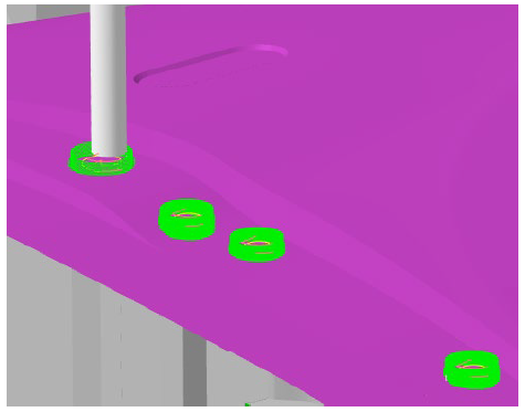 [Figure 4: Button die hole processing]
- Expansion of 3D design optimization function
- IoT-Visualization extension
The function to measure and visualize the actual conditions at the molding site has been expanded using IoT technology, and it is now possible
to display the amount of deflection for one shot (Note 4) in a color map and dynamically check changes in the amount of deflection. This
makes it possible to visualize in 3D space the sensor information that measures the amount of deflection of the bolster (Note 5) and lower die
during press molding, and to confirm the amount of deformation.
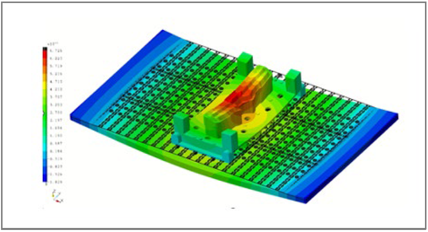 [Figure 5: Deformation display]
- Enhanced 3D Design Dedicated Functions for Molds
3DDL (Note 6): Scrap cutter line (Note 7) examination (press die)
A scrap cutter line examination function has been added. By entering conditions such as the maximum scrap size, the scrap cutter line considered by the system is automatically displayed, and the designer can make fine adjustments according to the image. We have improved the efficiency of the very time-consuming work in the die layout design.
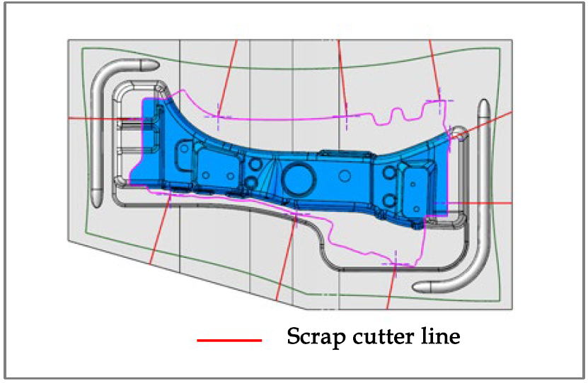 [Figure 6: Scrap cutter line study]
- 3D mold design: processing limit confirmation (press mold)
As a function to strengthen cooperation with the post-process, we have added a machining limit confirmation function that allows you to check in advance in 3D design data where machining cannot be performed due to tool interference. Based on information such as the size of the quill, sleeve, and tool part, the areas that cannot be machined can be checked on the 3D design data. It reduces processing defects and shortens the delivery time of mold manufacturing.
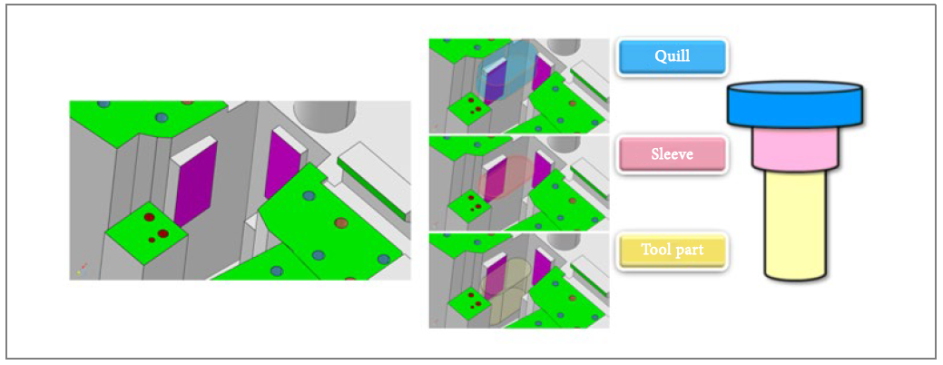 [Fig. 7: Processing limit confirmation]
- Mold release analysis function (resin mold)
We have enhanced the mold release analysis capability that allows us to consider and verify the causes and countermeasures for molding defects (deformation, whitening, etc.) that occur when releasing a resin product from the mold.
(1) Analyze only the cooling process among the cooling process/mold opening process/extrusion process
(2) Consideration of undercut part
(3) Designation of resin material
As a result, consideration of causes and countermeasures for products sticking to the cavity side (Note 8), and consideration of the ejector pin (Note 9) arrangement balance in areas where mold release resistance is strong on the core side (Note 8) can be made more accurate in a short time.
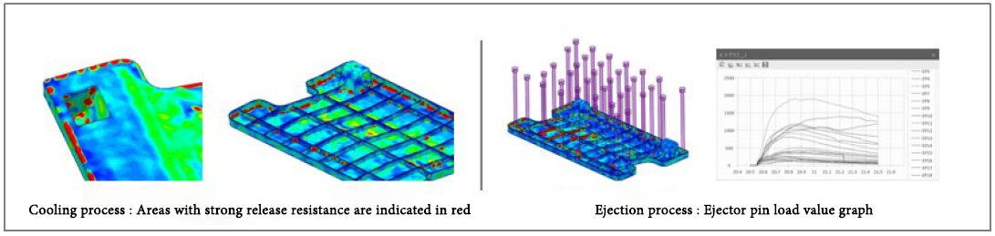 [Figure 8: Release analysis function]
- Intuitive operation and improved visibility
By reviewing the customer's work from various angles, we have achieved more intuitive operation and improved visibility of the 3D model. It provides a stress-free operating environment.
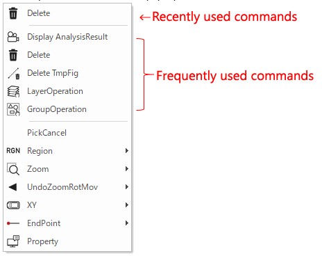
- Simplified command selection
“Recent commands" and "Frequently used commands" have been added to the pop-up menu to make it easier to select commands.
- Enhanced shading (Note 10)
The shading method options have been revamped, adding "smooth" and "animation" with different shades and light reflections. Material switching can now be done with a simple operation.
 [Figure 9: Simplification of command selection]
 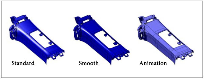 [Fig. 10: Enhanced shading]
In "CADmeister 2022", including customers who have already introduced CADmeister, we expect to sell about 5,300 licenses over the next year.
Note 1: Button die
One of the structures for punching holes in plate material with press-molded piercing dies. A member on the receiving side when drilling a hole to be installed in the lower die.
Note 2: Alignment of physical objects
When aligning the positions of objects, they are processed according to the dimensions of the object that actually exists. Also called Gengo.
Note 3: Scrap hole
A hole for dropping scrap punched out by a press-molded piercing die.
Note 4: One shot
One cycle from the top dead center to the bottom dead center when pressing a panel with a press machine, and then returning to the top dead center again.
Note 5: Bolster
A thick plate mounted on a press machine to fix the lower die of the press die.
Note 6: 3DDL
3D die layout. 3D design for process review, which is the initial concept of press die design.
Note 7: Scrap cutter line
A line that serves as a reference for members for finely cutting scraps (parts that are not needed for products) that are produced by trimming plate materials in the trimming mold during press molding.
Note 8: Cavity, Core
Parts that make up the mold for injection molding. The upper mold (concave side) is called the cavity, and the lower mold (convex side) is called the core.
Note 9: Ejector pin
"Ejector" + "Pin" = "extrude" + "bar", a rod-shaped part used to remove a plastic injection molded product from a mold.
Note 10: Shading
A technique that gives a three-dimensional effect to a 3D model by adding color and light-dark contrast in computer graphics drawing processing.
Powered by Froala Editor
Powered by Froala Editor
Powered by Froala Editor